- MAS8600/MAS8505/MAS8504 Graduate Foundations of Statistics and Data Science Report Briefing 2026-27
- HSC401 Academic Study Skills (T/505/9498) Assignment Brief 2026
- PS954 Research Methods in Psychology Lab Report Brief 2026 | University of Essex
- MS70121E Competitive Strategy & Innovation Assessment E2 Group Report 2026
- Unit 28 Cloud Computing Assignment : The Application of Cloud Computing to an Organization
- FBU4003 Understanding Principles of Business Assignment Case Study Report
- BUSI12334 Personal and Academic Development Level 4 Assignment 1 Fashion Sustainability Report
- Leadership and Management in Adult Care Assignment Report
- 425Z0087 Quantitative Data Analysis Secondary Data Analysis Semester 1 – Report Assessment Instructions & Information
- Criminology Assignment: Investigating the Representation of Ethnicity in Media Crime Reporting Versus Official Crime Data
- D7115 Technical and Digital Leadership Assignment: A Critical Analysis of Organisational Digital Readiness, Strategic Transformation Planning, and Leadership in Enabling Digital Change
- Level 5 in Leadership and Management in Adult Care – Unit 19 Assignment : Ensuring Health and Safety Compliance and Best Practices in Adult Care Settings
- N1582 Managing Operations Assignment : Enhancing Efficiency through ITO, 4Vs, Capacity Management, and Process Mapping
- MANM376 International Finance Project Assignment: Critical Analysis of Tata Steel, Godrej Properties, and LVMH’s Strategic Financial Decisions
- AB Sugar Company Strategic Management Assignment: External, Internal, SWOT & Sustainable Growth Strategy
- Unit 3 Project Assignment Report: Planning and Delivering a Professional Training Event to Develop IT, Leadership, or Soft Skills
- CIPD 5OS05 Level 5 EDI Strategy Report: Promoting Equality, Diversity and Inclusion in Public Sector Service Organisations
- Water Resources Assignment: HEC-RAS Flow Analysis and Hydraulic Jump Evaluation in Open Channels
- HRM Reflective Assignment 1: Case Study on Strategic Growth & Employee Retention
- AFM0ICD Budgeting Advice Assignment 1: Mr Confused Case Study on Business Budget Planning, Monitoring and Communication Using Microsoft Office Tools
ENG3036: Developing a mathematical model of the lateral dynamics of an aircraft approaching: Simulation Of Engineering Systems Report, UK
| University | University of Glasgow (UOG) |
| Subject | ENG3036: Simulation Of Engineering Systems |
Aim
Part 1 of this Simulation of Engineering Systems 3 Assignment involves the modeling, simulation, and validation of an Instrument Landing System (ILS) Lateral Beam Guidance System. This part of the assignment involves developing a mathematical model of the lateral dynamics of an aircraft
approaching using ILS for guidance. This model will be implemented in Matlab code and as a Simulink block diagram.
The responses from the Simulink block diagram will be used to analyze and validate the Matlab model and its associated simulation. This document provides background information about this system, followed by the problem specification for the mathematical model of the system and its simulation. Also, the Assignment Specifications are provided as a step-by-step guide for this part of the assignment.
Do You Need Assignment of This Question
Introduction
Most major airports have an ILS which can be used for automated or assisted landing of aircraft. Basically, this is a short-range navigational aid that provides azimuth (horizontal) and vertical position information. This assignment involves the development of a simulation of this system for lateral beam guidance as outlined in this document.
Background
The ground-based elements of ILS comprise a localizer transmitter, a glideslope transmitter, and marker beacons. These provide the azimuth, vertical, and distance signals respectively (see Figure 1).
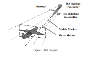
On the aircraft, there is a localizer antenna, a glideslope antenna, an ILS receiver unit, and a marker beacon antenna and receiver. The position of the aircraft relative to the localiser and glideslope is displayed on an indicator in the cockpit and is used to land safely.
The Localiser System
The localiser transmitter is positioned at the far end of the runway which the aircraft is approaching. It transmits on a given frequency in the band 108 MHz to 112MHz. The signals radiate to the left and right of the center line of the runway. The signal to the left is modulated by a 90 Hz component while the corresponding frequency for the signal on the right is 150 Hz. The two signals overlap in the middle. The autopilot uses the stronger overlapping signal region to position the aircraft within the ILS approach corridor.
Buy Answer of This Assessment & Raise Your Grades
The Glideslope System
The glideslope transmitter is located near the point of touchdown (threshold) on the runway and transmits on a given frequency in the range 329.3 MHz and 335.0 MHz. The radiated signal pattern is similar to that of the localiser but provides vertical guidance relative to a descent path.
The Marker Beacons
Marker beacon transmitters are located along the approach path and provide 75 MHz signals beamed vertically into the approach corridor. The beacons are located 7.4 km (outer marker) and 1.1 km (inner marker) from the runway threshold. These markers provide distance signals so that the speed of descent can be monitored and adjusted.
Are You Looking for Answer of This Assignment or Essay
If you are in need of engineering assignment help then no need to worry, Students Assignment Help UK is here. Our team of experienced professionals is here to help. We provide report writing help to students with their assignments every step of the way. Contact us today to get started!
Answer


