- Unit 2 Marketing Processes and Planning (A/618/5033) Assignment Brief 2026
- TMDIBS204 Managing people in a Multinational Context Assignment Brief 2026
- BMS508 Entrepreneurship Assessment 2 Brief 2026 | New College Durham
- BMS508 Entrepreneurship Assessment 1 Brief 2026 | New College Durham
- BUS6010 Business Transformation Assessment Brief 2026 | Arden University
- Unit 805 Strategic Communication (L/506/9129) Assignment Brief 2026
- Unit 803 Strategic Planning for Cross Border and Global Organisations (L/506/9132) Assignment Brief 2026
- Unit 806 Culture and its Impact on Strategy (J/506/9128) Assignment Brief 2026
- Unit 800 Leadership Qualities and Practice (A/506/9126) Assignment Brief 2026
- EFAW301 Emergency First Aid in the Workplace (R/650/4839) Assignment Brief 2026
- SOCI5006 Popular Culture, Media and Society Assessment 1, 2026
- Resource Management in Health and Social Care (A/618/5503) Assignment Brief 2026
- Health and Safety in Health and Social Care Settings (T/618/5502) Assignment Brief 2026
- Principles of Leadership and Management (M/618/5501) Assignment Brief 2026
- Unit 601 Developing Personal Effectiveness and Impact Assignment Brief 2026
- OTHM Level 3 Diabetes Awareness (D/651/7162) Assignment Brief 2026
- OTHM Level 3 Health Promotion (A/651/7161) Assignment Brief 2026
- Personal and Professional Development in Health and Social Care (F/618/5499) Assignment Brief 2026
- Managing Quality in Health and Social Care Settings (K/618/5657) Assignment Brief 2026
- BAM4052 Finance for International Business Assignment Brief 2026
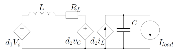
Derive and write the averaged model of the DC-DC Buck-Boost converter, as described in Figure: Intelligent Systems & Control Assignment, DMU, UK
| University | De Montfort University (DMU) |
| Subject | Intelligent Systems & Control |
Questions:
Part A:
- Derive and write the averaged model of the DC-DC Buck-Boost converter, as described in Figure. Consider as the measured output of the system the output voltage, equivalently, the voltage of the capacitor C).

- Linearise the model around the equilibrium point xeq=[20 0.4]T and derive the linearised state space representation.
- Provide several simulations of the averaged, nonlinear model and the linearised model you have acquired from questions 1 and 2 around the equilibrium point. Start by having as the initial condition the equilibrium point, and gradually use initial conditions that are farther away from it. You can use as constant input the input vector corresponding to the equilibrium point. Plot the time responses of the states for the two models against each other. Also, plot the trajectories of each model in the state space. Observe and report the differences, if any.
- Assuming a zero-order-hold discretization scheme, derive the discretized system from the linearised system, for a sampling period T=10μsecs. Compare the discretized version with the continuous-time system in a simulation, where the discretized system and the continuous-time linearised system are plots in the same figure.
- Compare also the state coming from the discrete approximation using Euler forward difference acting on the nonlinear system, i.e., by setting

Part B:
- Is the linearised continuous system controllable?
- Using the continuous-time linearised model, develop a stabilizing state space control law that drives the system to the equilibrium point. The closed-loop system must have a damping factor ζ=0.86 and a damped natural frequency ωd=2000.
- Simulate the open-loop linearised system and the closed-loop linearised system, and the closed-loop averaged system, for two initial conditions and observe/highlight the differences in the responses. Justify your choice of initial conditions.
Part C:
- The inductor current iL cannot be measured accurately without an expensive sensor. Thus, the controller designed in Part B cannot be implemented without an additional cost. To avoid this, we can develop an observer that estimates both states of the linearised system. Choose the eigenvalues of the closed-loop error dynamics of the observer and justify your decision.
- Write down the complete observer equation, that is the closed-loop error dynamics and the state estimate dynamics.
Part D:
- Consider the controller designed in Part B, which uses the state estimation instead of the actual states, as designed in Part C. Derive the resulting closed-loop system and write down the state equations and output equations. Is the resulting closed-loop system stable and why?
- Simulate two closed-loop systems with the controller designed in Part B by (i) taking the actual state as feedback and (ii) taking the state estimation as feedback. Observe differences if any.
Do You Need Assignment of This Question
Struggling to craft a unique and compelling case study? Students Assignment Help UK has the solution – a team of experienced, qualified assignment writers UK! They are ready to provide top-notch CIPD assignment assistance that will help you achieve your desired marks at an affordable price. Get ahead and make sure your work stands out from the rest – hire our experts today!
Answer


