- EN7068 Leadership, Stakeholders and Data Analytics Coursework Brief 2026
- ENGE2003 Engineering Project Management Coursework 2, 2026 | DMU
- 55-500223 Analogue and Digital Electronic Design Coursework Brief 2026 | SHU
- EGR9017 Power Systems Assessment Coursework 1 Brief 2026 | University of Lincoln
- 7BIOM037W Systems Biology Coursework 1 Report 2026 | University of Westminster
- NCFE CACHE Level 3 Unit 8 Professional Practice Portfolio 1 Coursework 2026
- NCFE CACHE Level 3 Unit 9 Supporting Emergent literacy Coursework 2026
- 6WBS0035/ 6WBS0036 Digital Economy CW1 Assignment Brief 2026 | UOH
- DSM060 Data Science Research Topics Coursework Assignment 2026 | UOL
- BARC0087 Structures Materials & Forming Techniques Coursework 2026 | UCL
- LL5306 Commercial Law Assessment Coursework Brief 2026 | Kingston University
- M22319 / M33098 Numerical Skills & Economics Assessment Coursework | UOP
- BMG872 Global Strategy Development and Implementation Individual Assignment CWK Brief 2026
- LLB020N204A Law of Property Assessment Coursework Brief 2026
- BS3397 Microeconometrics Coursework Assignment Brief 2026 | AU
- UMAD47-15-M Managing Finance Assessment Coursework Brief | UWE
- BST851 Business Data Analytics Assessment Coursework 2026
- MMM143 International Business and the World Economy Coursework 2026
- EMS402U Engineering Design Coursework Project Report 2026 | QMUL
- 25BSC565 Fundamentals of Strategic Management Coursework Brief
ME7732: Demonstrate a Good Understanding of the Functions of a Robot and its Embedded Systems such as Sensors and Actuators: Mechatronic Design and Automation Coursework, KU, UK
| University | Kingston University(KU) |
| Subject | Mechatronic design and automation |
Module Learning Outcomes
The following module learning outcomes and professional body learning outcomes are tested in this assessment:
Ø Demonstrate a good understanding of the functions of a robot and its embedded systems, such as sensors and actuators.
Ø Apply appropriate procedures to build dynamic models of robotics systems and design feedback control algorithms.
Ø Apply advanced techniques such as fuzzy logic and computer vision to optimize control in automation processes.
Assessment task and specific terms
The aim of this assignment is to extend your understanding of the main principles of robotic mechatronics systems including mechanical design, sensors, actuators, computer vision, and control strategies. Also, to integrate computer technology into a mechatronic product.
Inverted pendulum: design, model, build and control
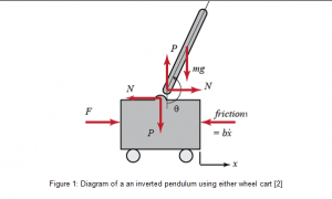
In this part, your group will design and simulate an inverted pendulum. The figure below shows an example of balancing an inverted pendulum by moving a cart along a horizontal track. Other implementations are also possible such as the Boxingbot which combines the structure of a mobile robot and an inverted pendulum system. You can also look into other types of inverted pendulums such as the Segway or overhead crane [1].
You have to develop an inverted pendulum model and controller. When put into its upper equilibrium position, the pendulum will be able to autonomously balance by returning to that position after (a ‘reasonable’) amount of disturbance is applied to the pendulum.
A wide range of sensors and actuators including servo motors, gyroscope sensor, angle sensor, accelerometer, ultrasound, colour sensor and camera should be investigated
Do You Need Assignment of This Question
A. TASK 1
Mechanical design and modelling
Note: Your mechanical design will affect both the electrical and control aspects of the system. Several designs may be adopted to achieve the inverted pendulum. Any change in the physical properties of the vehicle immediately cause changes in the system behaviour.
- Provide a short literature review including sketches of some potential designs.
- Describe the kinematics of the chosen mechanical design.
- Discuss the effects of the mechanical design on the dynamics of the system (e.g. the effect of the pendulum link length and mass, the effect of motor friction compared to other sources of friction, the effect of placement of components to adjust the centre of mass, etc.).
Figure 1: Diagram of an inverted pendulum using either wheel cart [2]
B. TASK 2
Sensors and actuators
There are a number of different sensors that can be used to measure the disturbance, including, angle sensor, gyroscope, accelerometer, ultrasound sensor, vision subsystem, light sensor and colour sensor.
- Provide investigation and document (including technical specifications) how each of the sensors works in theory.
- Compare the different sensors based on the investigation and assess their suitability for the task.
C. TASK 3
Computer vision
- Develop an algorithm using image processing techniques to identify the angle of disturbance to an inverted pendulum. Techniques may include image subtraction, filtering, and feature extraction such as Hough transform, colour processing or AI classification.
- Test your algorithms using both still frames with known angles and a video recording.
- Note that the default parameter settings are not necessarily the best. List the tunable parameters and explain how you set each one. Provide strategy to achieve the most accurate results.
- Comment on the accuracy and limitations of computer vision as a tool for the inverted pendulum task.
- Provide commented printouts of your m-files within the report
D. Task4
Modelling and Control
- Discuss the approximate linear model to describe the system (this involves taking into account relevant dimensions, weight and friction).
- Formulate a PID strategy capable of stabilising the inverted pendulum.
- Simulate in Matlab/Simulink and provide a critical discussion on the results.
- Provide the printout of commented m-files/Simulink diagrams.
E. Task5
Fuzzy control
- Formulate a Fuzzy logic strategy and implement it in Matlab.
- Explain the design and tuning process followed.
- Comment on the results.
- Provide the printout of the Fuzzy design.
- Compare and discuss the results with respect to task 4.
F. Task6
Demonstration – video programme performance test
- Record a video clip (maximum 6 minutes)including all the aspects of your design (A-E):
- Compare different designs and explain the most suitable approach
- Explain which sensors and actuators should be used for the real implementation.
- Describe your controllers and present simulations. Please note that conditions should include disturbances to be applied to the inverted pendulum that should be able to stabilise.
- Show the results of the computer vision program and explain the methodology adopted and parameter tuning.
Buy Answer of This Assessment & Raise Your Grades
Get the highest quality coursework writing help from native experts at StudentsAssignmentHelp.co.uk. our coursework writers have years of experience to write authentic and 100% error-free coursework solutions on engineering assignments. Hurry up and get a higher rank in Mechatronic design and automation coursework at a reasonable price.
Answer


