- Unit 2 Marketing Processes and Planning (A/618/5033) Assignment Brief 2026
- TMDIBS204 Managing people in a Multinational Context Assignment Brief 2026
- BMS508 Entrepreneurship Assessment 2 Brief 2026 | New College Durham
- BMS508 Entrepreneurship Assessment 1 Brief 2026 | New College Durham
- BUS6010 Business Transformation Assessment Brief 2026 | Arden University
- Unit 805 Strategic Communication (L/506/9129) Assignment Brief 2026
- Unit 803 Strategic Planning for Cross Border and Global Organisations (L/506/9132) Assignment Brief 2026
- Unit 806 Culture and its Impact on Strategy (J/506/9128) Assignment Brief 2026
- Unit 800 Leadership Qualities and Practice (A/506/9126) Assignment Brief 2026
- EFAW301 Emergency First Aid in the Workplace (R/650/4839) Assignment Brief 2026
- SOCI5006 Popular Culture, Media and Society Assessment 1, 2026
- Resource Management in Health and Social Care (A/618/5503) Assignment Brief 2026
- Health and Safety in Health and Social Care Settings (T/618/5502) Assignment Brief 2026
- Principles of Leadership and Management (M/618/5501) Assignment Brief 2026
- Unit 601 Developing Personal Effectiveness and Impact Assignment Brief 2026
- OTHM Level 3 Diabetes Awareness (D/651/7162) Assignment Brief 2026
- OTHM Level 3 Health Promotion (A/651/7161) Assignment Brief 2026
- Personal and Professional Development in Health and Social Care (F/618/5499) Assignment Brief 2026
- Managing Quality in Health and Social Care Settings (K/618/5657) Assignment Brief 2026
- BAM4052 Finance for International Business Assignment Brief 2026
B50EM: Compare and contrast the design principles for wind turbines and tidal turbines. Your review should focus on the sizing: Advanced Mechanics of Materials I Assignment, HWU, UK
| University | Heriot-Watt University (HWU) |
| Subject | B50EM: Advanced Mechanics of Materials I |
Part 1 – Review of Energy-Generating Turbine Blade Design
Compare and contrast the design principles for wind turbines and tidal turbines. Your review should focus on the sizing, geometric design, and materials of construction of the blades and should consider the changes in the design dictated by the different types of loading involved.
Part 2: Analytical design
Use two simple models of a blade, assuming it to be a rectangular sheet with either one end or the edge fixed, as illustrated in Figure. Stack the upper and lower surfaces of sector 2 on top of each other to make a single laminate.
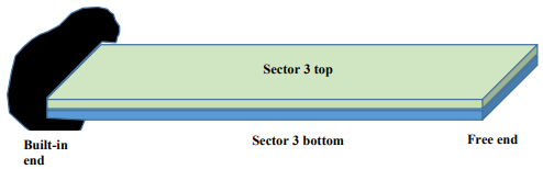
Fig. A- Simplified flap-wise model of Sector 2
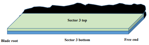
Fig. B- Simplified edgewise model of Sector 2
Using a [0/45/90/-45]2s lay-up carbon fiber epoxy laminate for the two surfaces stacked together, determine appropriate values of Vf and thickness for the plies to ensure that the composite meets the design deflections under the anticipated peak current loading4 and meets the Tsai-Hill strength criterion with an appropriate factor of safety. Carry out the calculation for each model, and select the lay-up that you consider is the more appropriate of the two.
Part 3: Numerical design
Using the orthotropic modulus from Part 1, build FE model of the simplified configurations you used (Figures A and B) and validate your flapwise and edgewise deflections under the maximum current loading that you used in Part 1. Next, using the material that you designed in Part 1, apply both the edge and end fixities simultaneously. Again, apply the maximum current loading and determine the resulting edgewise and flapwise deflections. Reserve your comments on this result for Part 4.
Part 4: Damage mechanics and fatigue
Using the orthotropic modulus and simplified model from Part 1, but using selected values of mid-surface curvature from Part 2, assess the fatigue life of the blade, assuming an R-ratio of -1, and what you consider to be an appropriate value of stress range. Use the Goodman diagram given in Figure.
Make suggestions for changes to your material design and suggest a full-scale fatigue testing regime for a prototype blade.

Goodman diagram for [0/45/90/-45]2s carbon fibre epoxy laminate
Do You Need Assignment of This Question
Looking for a coursework writing service that delivers quality work at an affordable price? Look no further than StudentsAssignmentHelp.co.uk! Our assignment writing experts will provide tailored solutions to meet all your academic needs, enabling you to achieve success without breaking the bank.
Answer


