Use Thevenin’s theory to simplify the 15v single source network shown below. The load resistor is given as 14Ω.: Engineering Science Assignment, UK
| Subject | Engineering Science Assignment |
Part 2a
- Use Thevenin’s theory to simplify the 15v single source network shown below. The load resistor is given as 14Ω. Determine the terminal voltage and current drawn.

Buy Answer of This Assessment & Raise Your Grades
- Use Norton’s theory to simplify the 6v/3v two source network shown below. A load resistor of 4.7k is placed across A-B. Determine the terminal voltage and current drawn.

-
- the amplitude of the fundamental;
- the frequency of the fundamental;
- the order of any harmonic components present;
- the amplitude of any harmonic components present;
- the phase angle of any harmonic components present (relative to the fundamental).
- A complex waveform is given by the expression:
i = 5 sin(50pt) + 3 sin(200pt – p /2) + 1.5 sin(500pt – p/2) mA
Describe using the above example:
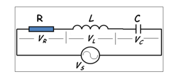
- An ac circuit with a 80 μF capacitor in series with a coil of resistance 16Ω and inductance 160mH is connected to a 100V, 100 Hz supply is shown below. Calculate
- the inductive reactance
- the capacitive reactance
- the circuit impedance and V-I phase angle θ
- the circuit current I
- the phasor voltages VR, VL, VC and VS
- the resonance circuit frequency
Also construct a fully labeled and appropriately ‘scaled’ voltage phasor diagram.

Part 2b
- Explain the principles of electromagnetic induction and how they apply to ac electrical machines such as motors, generators and transformers.
- Two coils have a mutual inductance of 0.2H. If the current in one coil is changed from 10A to 4A in 10 ms, calculate (a) the average induced e.m.f. in the second coil, (b) the change of flux linked with the second coil if it is wound with 500 turns.
- A coil, having a resistance of 20 Ω and an inductance of 0.0382 H, is connected in parallel with a circuit consisting of a 150 μ F capacitor in series with a 10 Ω resistor. The arrangement is connected to a 230 V, 50 Hz supply. Using the method used in 2a, determine the current in each branch and the total supply current.
- Construct a fully labelled, scaled phasor diagram to determine the total current
- Evaluate both techniques to solve problems, on series-parallel R, L, C circuits by commenting on the pros and cons of each.
Are You Looking for Answer of This Assignment or Essay

Navigating your Engineering Science Assignment in the UK? Explore our specialized online assignment help in UK. With tailored engineering assignment writing services, we’re dedicated to aiding UK students in their academic journey. Trust our experts to handle your assignments while you focus on mastering your course. Say farewell to academic stress – reach out today for unparalleled assistance and elevate your academic performance!


