- EN7068 Leadership, Stakeholders and Data Analytics Coursework Brief 2026
- 55-500223 Analogue and Digital Electronic Design Coursework Brief 2026 | SHU
- EGR9017 Power Systems Assessment Coursework 1 Brief 2026 | University of Lincoln
- 7BIOM037W Systems Biology Coursework 1 Report 2026 | University of Westminster
- NCFE CACHE Level 3 Unit 8 Professional Practice Portfolio 1 Coursework 2026
- NCFE CACHE Level 3 Unit 9 Supporting Emergent literacy Coursework 2026
- 6WBS0035/ 6WBS0036 Digital Economy CW1 Assignment Brief 2026 | UOH
- DSM060 Data Science Research Topics Coursework Assignment 2026 | UOL
- BARC0087 Structures Materials & Forming Techniques Coursework 2026 | UCL
- LL5306 Commercial Law Assessment Coursework Brief 2026 | Kingston University
- M22319 / M33098 Numerical Skills & Economics Assessment Coursework | UOP
- BMG872 Global Strategy Development and Implementation Individual Assignment CWK Brief 2026
- LLB020N204A Law of Property Assessment Coursework Brief 2026
- BS3397 Microeconometrics Coursework Assignment Brief 2026 | AU
- UMAD47-15-M Managing Finance Assessment Coursework Brief | UWE
- BST851 Business Data Analytics Assessment Coursework 2026
- MMM143 International Business and the World Economy Coursework 2026
- EMS402U Engineering Design Coursework Project Report 2026 | QMUL
- 25BSC565 Fundamentals of Strategic Management Coursework Brief
- MARK5025 Contemporary Marketing Communications Assessment Coursework Brief 2
ENGE2003 Engineering Project Management Coursework 2, 2026 | DMU
| University | De Montfort University (DMU) |
| Subject | ENGE2003 Engineering Project Management |
ENGE2003 Coursework 2 (ME, AE, MX)
Lab 3 – Bicycle Crank Design, Simulation and Optimisation
Purpose
To demonstrate engineering judgement in design optimisation through the use of CAD, finite element analysis, and mechanical reasoning. This includes estimating realistic loads, applying appropriate boundary conditions, improving computational efficiency, and communicating the final design using a professional engineering drawing.
Instructions
- Read this lab sheet carefully, including all figures, tables, and marking criteria.
- Using Creo Parametric and ANSYS Mechanical, design, analyse, and optimise a bicycle crank. Finite element analysis must be used to inform design decisions and improve the efficiency of the final solution.
- For this task, you are required to calculate the load applied to the bicycle crank based on the mass of the rider. This load must be justified using basic mechanics and applied consistently in all simulations.
- You must clearly state all assumptions made when determining the applied load.
- Optimisation must be achieved through controlled design or modelling decisions and supported by quantitative simulation evidence. Submit your completed report and associated files via the Virtual Learning Environment (VLE) by the published deadline.
Learning Outcomes
On successful completion of this laboratory, students will be able to:
- Demonstrate an understanding of the criteria for workable and good engineering design and the ability to use relevant resources (e.g., CAD, simulation software, analytical tools) to create, evaluate, and optimise a virtual engineering solution. [AHEP4: C2, C3, C4, C6]
Assessment Weighting
- This laboratory contributes 40% of Coursework 2.
- A detailed marking rubric is provided at the end of this lab sheet.
Feedback on This Assessment
- Feedback will be provided against the published marking rubric.
- Feedback will normally be returned within 15 working days of submission.
- Students are encouraged to use this feedback to improve their design, simulation, and engineering judgement in subsequent assessments.
Design Specification
The bicycle crank must be designed to meet the client specification given in Table 1. This specification defines the functional, structural, environmental, and aesthetic requirements for the component and must be considered throughout the design, analysis, and optimisation process.
The final design must comply with the design envelope shown in Fig. 1 and satisfy the safety and performance requirements outlined below.
Table 1: Bike crank design specification
| Parameter | Requirement | Achieved Yes/No | Evidence |
| Performance | Client weight is 70 Kg
Max component weight is < 300 g. |
||
| Size | Max footprint detailed in Fig.1. | ||
| Maintenance | No maintenance during lifespan. | ||
| Finish | Corrosion resistant. | ||
| Materials | Easily recyclable. | ||
| Transportable | Not easily damaged by impact. | ||
| Aesthetics | Must present an image of high-end performance. | ||
| Customer | BMX enthusiasts. | ||
| Safety | Should not have any sharp protrusions, safety factor of 2 implemented from design loading. | ||
| Environment | -10 to + 40 deg C, water, and dust resistant. | ||
| Ergonomics | Compatible with existing mounts and peddles. |
Archer’s Design Process
Your report must be structured using Archer’s Design Process, as outlined below.
Stage 1 – Analysis
This stage demonstrates understanding of the design problem, constraints, and loading.
1.1 Design Brief and Client Requirements
Interpretation of the bicycle crank design brief with reference to the client specification in Table 1.
1.2 Design Constraints and Envelope
Identification and explanation of key constraints, including:
- design envelope and fixed interface regions
- mass limit
- safety factor requirement
- intended user group
1.3 Conceptual Design and Decision Making
Before detailed CAD modelling, you must demonstrate conceptual design thinking and justify key design decisions. This section should include:
- One or more initial design concepts, illustrated using sketches, annotated screenshots, or schematic diagrams
- Explanation of how the concepts address the client specification, design envelope, and safety requirements
- Justification of major design decisions, such as:
o overall form and load path
o material choice
o regions where material may be removed or retained
o balance between stiffness, strength, mass, and aesthetics
Conceptual designs do not need to be dimensioned. Marks are awarded for clarity of reasoning and justification, not artistic quality.
1.4 Load Calculation and Assumptions
Calculation of the applied load based on the client rider mass (70 kg), including:
- stated assumptions
- working and units
- explanation of how the load is applied in the FEA model
For higher marks, consideration of the pedal-induced moment about the crank axis should be demonstrated and justified
Stage 2 – Synthesis
This stage demonstrates development and refinement of a design solution.
2.1 Baseline Design Development
Description of the initial CAD model, demonstrating compliance with the design envelope and suitability for comparison.
2.2 Simulation Setup
Explanation of material selection, boundary conditions, and meshing strategy used for analysis.
2.3 Design Optimisation
Description of the optimisation strategy, including controlled geometry or modelling changes made within the design envelope.
Optimisation must demonstrate improved material efficiency and be supported by quantitative simulation evidence.
Stage 3 – Evaluation
This stage demonstrates critical evaluation of the final design.
3.1 Results and Comparison
Comparison of baseline and optimised designs, including stress results, factor of safety, and mass.
3.2 Validation Against Specification
Evaluation of the final design against the client specification, including mass, safety factor, and envelope compliance.
3.3 Engineering Judgement and Reflection
Justified discussion of design decisions, trade-offs, limitations, and remaining risks in the final design.
Engineering Drawing Requirement
You must submit a fully dimensioned engineering drawing of the final optimised bicycle crank.
- The drawing must comply with BS 8888 conventions
- The drawing must define all key dimensions and interfaces
- The drawing must respect the design envelope and fixed interface regions
Submission Requirements
- Design report (PDF, structured as above)
- Engineering drawing (PDF)
Submission Notes
- Reports should be written in a clear, professional engineering style
- All figures, tables, and calculations must be clearly labelled
- Results must be consistent with the stated loading and assumptions
- Unsupported or generic discussion may limit the maximum mark achievable
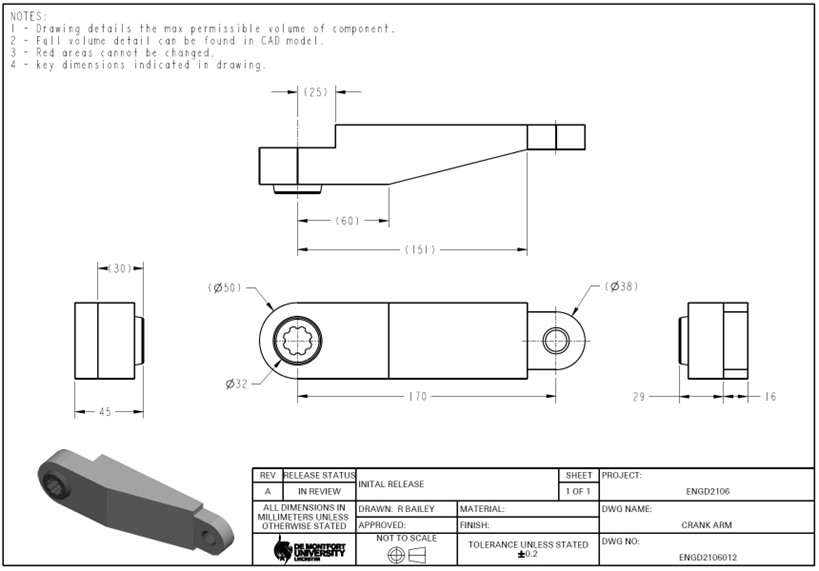
Figure. 1: Engineering drawing of the working volume and the attachment geometry. A step file of this geometry can be found on the VLE.
ENGE2003 Making Rubric
| Criterion | Weight | First Class (70–100%) | Upper Second (60–69%) | Lower Second (50–59%) | Third / Pass (40–49%) | Fail (<40%) |
| Report structure & presentation | 10% | Exceptionally well-structured and professionally presented Level 5 technical report. Includes title page, contents page, page numbers, clearly numbered figures with relevant captions, welldefined sections with headings, clear sentence structure, and correct IEEE referencing throughout. | Very well-structured report with most required presentation features present. Figures and sections are clear with only minor formatting or referencing issues. | Well-structured report with most key presentation elements present. Some inconsistencies in formatting, captions, or referencing, but overall communication is clear. | Satisfactory attempt at structuring the report. The work is readable and logically ordered, but several presentation elements are missing or unclear. | Poorly structured report. Presentation significantly detracts from clarity, making the work difficult or impossible to follow. |
| Design conceptualisation & decision making | 10% | Exceptional range of initial design concepts presented. Clear evidence of conceptual design thinking and justified decision-making prior to detailed modelling, informed by the client specification and design envelope. Selection criteria are clearly defined and well reasoned. | Particularly good range of design concepts with clear justification and appropriate selection criteria. Decisions are well reasoned and mostly specification-driven. | Good range of design concepts presented. Design justification is present but may lack depth or breadth in selection criteria. | Some initial design concepts shown, but justification of decisions is limited or partially unclear. | Design concepts not shown or not meaningfully justified. No clear rationale for the chosen design. |
| Boundary
conditions, loading & discretisation |
10% | Boundary conditions and loading accurately represent the client specification. Load is correctly derived from the rider mass with clearly stated assumptions. For higher marks, the pedal-induced moment is correctly identified and appropriately accounted for. Mesh is well refined, material properties clearly presented, and mesh independence demonstrated to a high standard. | Boundary conditions and loading are appropriate and match the specification. Load derivation is explained and applied correctly. Mesh strategy is clear, with some evidence of refinement. | Boundary conditions and loading mostly match the specification. Load calculation is present but assumptions or application may lack clarity. Mesh strategy is basic. | Boundary conditions applied with some limitations. Load applied but justification is weak. Mesh present but not optimised. | Little or no discussion of boundary conditions, loading, or mesh. Load incorrect, unjustified, or inconsistently applied. |
| Initial analysis results & discussion | 15% | Initial analysis results are exceptionally well documented and clearly presented. Results are discussed with strong engineering insight. Factor of safety is correctly evaluated, with clear identification of areas for optimisation. | Results are very well documented and discussed with good insight. Factor of safety evaluated with optimisation opportunities identified. | Results are well documented but discussion lacks depth or insight. Factor of safety evaluated, but interpretation may be limited. | Results presented with basic discussion. Some errors or gaps in interpretation. Factor of safety may be inconsistently addressed. | Results missing, poorly presented, or not discussed. |
| Optimisation & conclusions | 25% | Optimisation is exceptionally well thought out and demonstrates strong understanding of efficiency-driven design. Design changes are controlled and fully contained within the design envelope. Optimisation is clearly linked to analytical theory and simulation evidence. Conclusions clearly summarise outcomes and confirm performance requirements are met. | Optimisation is very well considered and shows good understanding of the process. Design meets performance requirements, with reasonable analytical justification. Conclusions summarise outcomes effectively. | Some optimisation attempted and partially justified. Design meets most specified targets. Conclusions present but may lack depth or clarity. | Limited optimisation attempted. Design is close to meeting targets but lacks strong justification. Conclusions present but superficial. | Little or no meaningful optimisation conducted. Conclusions missing or inadequate. |
| Engineering drawing | 30% | Outstanding engineering drawing compliant with BS. Fully dimensioned with clear orthographic projections, appropriate section/detail views, and a complete title block. Drawing clearly communicates the final optimised design and respects the design envelope and fixed interface regions. | Excellent drawing with very good clarity and near-complete title block. Most key dimensions included, with effective use of views. | Good drawing that communicates design intent, though some dimensions, views, or title block information may be missing. | Satisfactory drawing with some clarity issues, missing views, or errors in dimensioning. Design intent still recognisable. | Unsatisfactory drawing. Poor communication of design, non-compliance with standards, or not submitted as a PDF. |
Submit High-Quality ENGE2003 Engineering Project Management Coursework Answer With Expert Help
If you are facing difficulties with your ENGE2003 Engineering Project Management coursework—especially while working on CAD design, FEA simulation in ANSYS, and optimisation of the bicycle crank—you’re not alone. Many students prefer Students Assignment Help for expert engineering assignment help aligned with your coursework requirements. You can also explore DMU assignment questions for better clarity. Get started today with our assignment help online and receive a fully customised, human-written, plagiarism-free solution.
Answer


